
Repairing an ECU/ECM is a highly technical process that requires electronics knowledge, diagnostic equipment, soldering skills, and automotive ECM/ECU repair is a specialized process that requires proper tools, careful diagnostics, and safe electronic handling. This guide explains every step of the ECM/ECU repair procedure so technicians can diagnose, repair, and restore an engine control module correctly.
1. Tools and Materials Needed for ECM/ECU Repair
- Automotive OBD-II diagnostic scanner
- Bench power supply (12–14V)
- ECU pinout diagrams
- Multimeter
- Oscilloscope
- Soldering/rework station
- EEPROM/Flash programmer (KESS3, KTAG, PCMFlash, Autotuner)
- ECU bench harness
- Replacement MOSFETs, voltage regulators, capacitors, drivers
- Contact cleaner
- ESD-safe workstation
2. Safety Precautions for ECM/ECU Repair
- Disconnect the vehicle battery before removing the ECU
- Work on an ESD-safe environment
- Do not touch the PCB with bare hands
- Confirm correct pinout before applying power
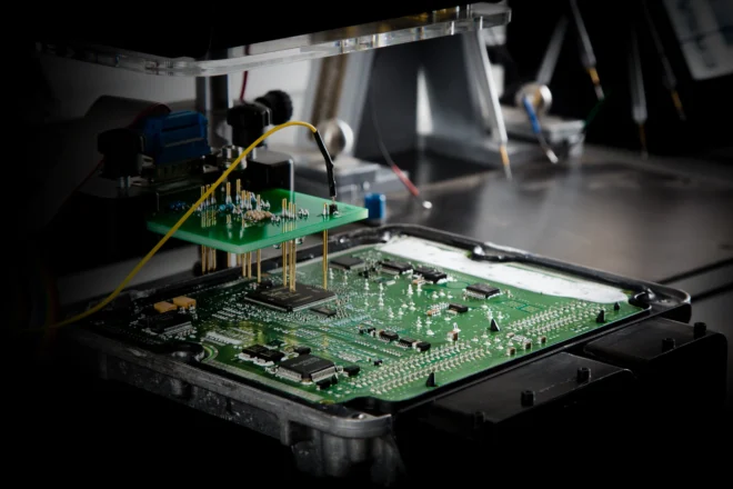
3. Removing the ECU for ECM/ECU Repair
- Locate the ECU (engine bay, cowl, under dash)
- Disconnect harnesses carefully
- Remove mounting bolts and extract the ECU
4. Initial Diagnostic Testing Before ECM/ECU Repair
Connect a professional scanner and check for:
- No start
- No communication (U0100)
- Misfires
- Injector/coil driver faults
- Power supply issues
- Immobilizer lock
This narrows down what type of ECM/ECU repair is needed.
5. Visual Board Inspection During ECM/ECU Repair
Open the ECU and inspect for:
- Burnt or blown components
- Water intrusion or corrosion
- Cold solder joints
- Cracked capacitors
- Damaged MOSFETs
- Rusted connectors
- Broken PCB traces
Clean corrosion carefully with contact cleaner.
6. Power Supply Testing in ECM/ECU Repair
Use a multimeter to confirm:
- 12V main power input
- 5V regulator output
- 3.3V logic supply
- Ground continuity
- Injector/coil driver voltage
Most ECM/ECU repair cases involve power circuit failure.
7. Component-Level ECM/ECU Repair
Replace components such as:
- Power drivers
- MOSFETs
- Voltage regulators
- Diodes
- Capacitors
- Micro relays
- Transistors
Use quality parts and add thermal paste where required.
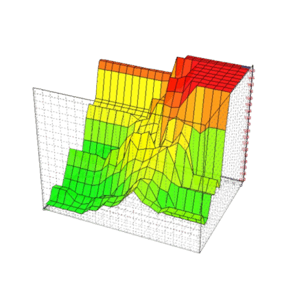
8. EEPROM & Flash Memory Repair in ECM/ECU Repair
If firmware is corrupted:
- Use KTAG, KESS3, PCMFlash, Autotuner
- Read EEPROM + Flash
- Fix checksums
- Restore IMMO, VIN, ISN
- Rewrite firmware
- Replace memory chips if physically damaged
This is a common step in advanced ECM/ECU repair.
9. Bench Testing After ECM/ECU Repair
Use a correct bench pinout to test:
- 12V power input
- CAN communication
- Sensor reference outputs
- Injector/coil driver signals
- IMMO communication
An ECU must behave like it does in the vehicle.
10. Reinstallation After ECM/ECU Repair
- Reinstall ECU
- Reconnect harness
- Reconnect the battery
11. Final Vehicle Testing After ECM/ECU Repair
Verify:
- Engine starts immediately
- No fault lights
- Stable idle
- Proper injector firing
- Normal throttle response
- Correct sensor readings
- Boost operation (turbo vehicles)
Important Notice About ECM/ECU Repair
ECM/ECU repair should only be performed by trained electronics technicians. Incorrect procedures can damage coils, injectors, power circuits, or the entire electrical system. If you are not comfortable with micro-soldering or ECU flashing, professional repair services like FixECM are recommended.
Additional Resources
Contact FixECM
📞 647-247-8555
📞 1-800-915-5566 (Toll-Free)
📧 info@fixecm.com
🌐 https://www.fixecm.com